News
Getting a great first layer, an important foundation for reliable 3D printing. (and super important for gliders!) September 15 2017
Getting a solid, smooth first layer is a key part of producing high quality prints. The first layer forms the critical foundation for your model, and can determine the success or failure of your print even long after the start of the printing process. Some models, such as the flying gliders here at threedsy.com, rely on a smooth first and second layer for both performance and durability.

The foundation of all 3d prints is a good first layer. First layer performance becomes even more important when printing thin structures like the wings on the high performance flying gliders available here at threedsy.com.
So, How do you print a smooth, reliable first layer? First, you will need a good printing surface that will adhere to the plastic you are printing. A PEI sheet, Build-tack, Kapton tape, glass with hairspray or glue stick, or many other solutions might work for you, depending on the machine you use and the filament that you wish to print with. My strong preference if for a PEI sheet, though adhesion with ABS is not as good as it could be.
Next, you will need to have the z-height accurately adjusted, and to be sure that your extrusion rate is accurate for your filament and extruder drive system. The exact method of adjusting the z-height zero point varies considerably from printer to printer, so I will not be addressing that directly – (you should refer to your manual for the adjustment method). Instead I will focus on tuning and testing to ensure that everything is where it needs to be.
First, warm your printer to printing temperature. Set your heated bed (if equipped) and nozzle to standard printing temperatures. You may want to retract a bit of filament to prevent oozing. Preheating is important, because the nozzle and bed can change shape slightly depending on the temperature.
Next, download this Z-Height test model. Slice it to print in the middle of the print bed with a 0.15 layer height, one lower and two upper surfaces (ideally) or two upper and two lower (0.3mm) surfaces if selecting different thicknesses for the top and bottom is not an option. Use one or two perimeters, and a 30% line infill.
After the printer is up to temperature and thermally stable (15 minutes or so) , roughly set the z-height of your printer. It may do this automatically, or you can use the manual adjustment to bring the nozzle down (bed up) to where a piece of notebook paper slides easily between the nozzle and the bed, but not completely freely...it should have a little friction.
After this initial adjustment, print the test model in the very center of the print bed. Examine the result. It should be smooth but solid. If there are spaces between the print lines on the lower (outer) step, the nozzle is too high. If there are gouges or marks / ribbons on the surface of the lower step, the nozzle is too low. Adjust your zero point as per your printer manual or build resource until the lower step is smooth and solid. When peeled up, the bottom should be smooth with barely discernible lines but no cracks or separations. If there are no lines at all on the bottom, the nozzle may be still slightly too low, or you may just be exactly on the sweet spot if the top is nice and smooth.
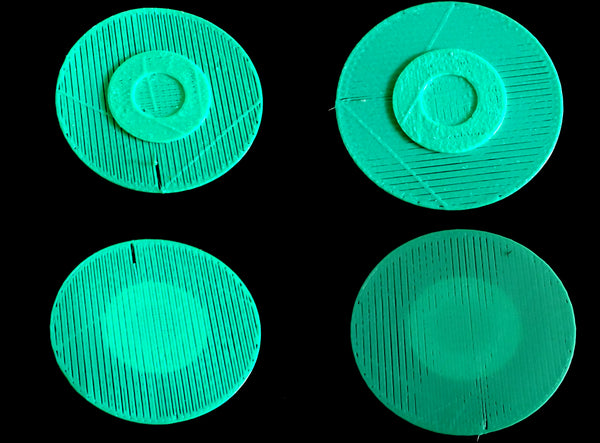
Above, typical results when the nozzle is too far from the print bed. Notice the un-fused lines, sieve like appearance, and the way that the print improves on the upper layers, indicating the problem as a first layer issue. The lines are from oozing during travel, as these pieces were printed without retraction to better illustrate the differences.

Here you can see, typical results when the nozzle is too close to the print bed. Notice the low areas where the nozzle was sealed by the print bed, and the ribbon like artifacts that squeezed out beside the head during printing. Once again, the print improves on the upper layers indicating the problem as a first layer issue.
Once the bottom step (first layer) is solid, without ribbons, gaps, or gouges, turn your attention to the upper layers.
With a good first layer but sieving at the upper layers as shown on the left in the following photo, your filament is either smaller than your settings, slipping in the extruder drive, your E-steps are too low, or your Z-axis steps are too high. Conversely, If the first layer looks good but upper layers show ribbons or gouging, your filament is probably larger than the setting, the E-steps are too high, or the Z-steps are too low. If your filament diameter is correct, your Z axis moves the distance it is commanded, and your extruder drive is feeding correctly, try adjusting the extrusion multiplier “fudge factor” setting.
Most of the time incorrect filament size is the cause. Measuring your filament diameter and giving the slicer correct information is critical to getting good results.

Shown above is an example on the left of underextrusion, and on the right of overextrusion. Note how in both cases the first layer is reasonably well adjusted, but the upper layers degrade in quality. In a properly calibrated printer, these problems are usually a result of variations variations in filament size, or sometimes in the case of underextrusion (left) due to extruder drive slippage.

Shown here is a reasonably good test example. Note the slight overextrusion near the ends of the print lines. Depending on your printer and software, these may be a normal result of minor imperfections in the acceleration algorithm or due to bonding overlap between the edge and the fill of the layer.
Once you can get a reasonably good first layer in the center of your print bed, the next step is to adjust your bed to be perpendicular to the z-axis (usually called bed “leveling”). This should enable you to get a good first layer on the entire print bed. Most heated beds bulge up a little in the center due to temperature distribution variations, so precise control of this will likely require software compensation for bed irregularities. Thankfully, this feature is built into most modern firmware...if your printer doesn't have it, look into any firmware updates that could provide this important capability.
WoW! much fly, little coin! January 30 2014

To pay with doge, just send an email to sales@threedsy.com with your order details, and transfer your doge payment to the threedsy.com wallet :
DSU7DExz8vfV7E56Kvxvd27iPhZUcpLRTK

To The Moon!
Manta ray October 10 2013

extrusion multipliers and printing engineered structures - a technical brief October 10 2013
In FDM (fused deposition manufacturing) printers like the REPRAP and related designs, the amount of filament that the extruder deposits through the print nozzle while printing is one of the most critical factors. The calculation to arrive at the correct amount of filament to feed will be dependent upon the feedstock filament size and variability, the nozzle diameter, the extruder drive wheel tension, the extrusion temperature, and the layer height (+/- any first layer corrections).
excessive material deposition caused these lumpy surfaces, most evident
where the fill ratio is 100% and there is no place for excess to go.
Sometimes, insufficient first layer height can be the actual cause
on thin structures such as this.
For aircraft and other objects where the interaction of the internal and external structure of an item works together to provide a desired function, significant deviations from optimal extrusion may cause unacceptable performance characteristics in the finished print.
Many of the aircraft designed by Handmade By Robots here at threedsy.com are engineered to flex in very specific ways in response to environmental factors such as airspeed, g-loading, gravity, and -especially in the case of the cumulus- even air currents and thermals (it is designed to resist the natural tendency to turn our of buoyant air by twisting at the wingtips).
The flying wing series develops its proper airfoil and reflex shape by a complex interaction of bending forces created when the dihedral clip, the wing hinge, the unhinged portions of the wing, and the vertical stabilizers / reflex formers interact in the assembled model.
Due to these design considerations, as well as cosmetic factors, it is highly desirable to optimize the extrusion process as much as possible so as to preserve the designed in flight characteristics, minimize weight, and to end up with an attractive, true flying model.

A small deficit of material causes the upper surface to fuse
incompletely, resulting in porosity and a lack of rigidity.
Assuming that your extruder is properly calibrated in the firmware, and the G-code generating program you use has good numbers for your filament and nozzle size, a reasonably midrange extrusion temperature, and an accurate idea of the actual first layer height, you should get reasonable extrusion quality barring problems with extruder drive function or adjustment.
For -optimal- printing, such as may be required for highly engineered pieces (such as functional items, or items designed to flex in very specific ways, such as aircraft) some fine tuning may be required. The goal is to deposit just enough material to provide solid fill of solid objects, without excess or voids of any kind. In practice, this can be very difficult, as feedstock filament size has some variability, and this variability is magnified and directly expressed in the extrusion process.
The "fudge factor" used to compensate for minor mis-calibration or filament variation is the "extrusion multiplier", a simple factor applied to the overall extrusion calculation, so that 1 equals no adjustment, .95 causes a 5% reduction in filament feed, and 1.05 provides a 5% increase in feed.
In practice, a slight deficit of material is preferable to excess, which builds up on the print and can accumulate to the extent that if can cause a print head crash, ruining the print , or in less severe cases results in a globby surface. As long as the deficit is just enough to compensate for filament variability, and the filament is also reasonably uniform, any deficit or voids in the final piece will be negligible. On the other hand, if the material deficit is excessive, flimsy prints, unclosed surfaces, poor bed adhesion, and porous structures may result.
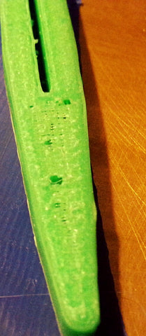
Insufficient extruded material caused these voids. In this case,
it was caused by insufficient tension on the extruder drive wheel springs.
One way to determine the proper "fudge factor" for a given combination of filament, nozzle, and extruder is to print a solid object at 100% fill. gradually increase the extrusion multiplier (by .02-.03) until the print starts to develop surplus material, which will typically be evident at the edges first as the print becomes more "messy". Then retry while reducing the multiplier by .01-.02 until the print is once again uniform. This should be close to optimal, although filament variability may cause you to back off another .01-.02 if excess material occasionally appears.
At this point you may have to readjust your first layer height multiplier to reflect the inverse of your extrusion adjustment (for example, if you -increased- extrusion by 3%, you will need to make an equivalent -reduction- at the first layer adjustment.
Having a correct extrusion calibration / multiplier will help you to make clean, high quality engineered objects that fit together and provide the performance characteristics with which they were designed.
Snap together! September 30 2013
An exciting new development in our design process is the addition of snap-fit models. The glueless construction simplifies assembly, but requires pretty clean dimensional performance from your printer. If your printer is well calibrated and makes pretty good corners, these should work for you.
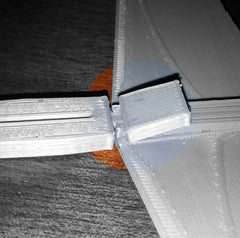
On models that use a dihedral clip, it is helpful
to attach the clip corner first, while holding the
dihedral hinge tightly closed, then slide the clip
all the way forward until it stops or clicks into place.


3D Printing airplane wings and other membrane structures May 27 2013
When printing very thin (1-4) layer structures with FDM printers, special issues are sometimes encountered.
Temperature:
It is often helpful to use a slightly higher (3-7 deg C) than normal temperature for the first layer to enhance print leveling, reduce nozzle pressure, and to improve adhesion. Be careful not to raise the temperature to the point where decomposition of the thermoplastic begins, as this can cause nozzle clogging and degraded print quality.
Adhesion:
You will need a bed surface with good adhesion qualities. It must be flat, free of skin oils, and clean. For ABS, Kapton tape cleaned with CPVC-PVC-ABS pipe cleaner compound works well. For PLA, Kapton adhesion is often poor, and can be improved by dissolving a small amount of ABS filament with the solvent swab and wiping down the bed surface with the resulting mixture. Beware that this process will result in extreme adhesion for ABS prints.
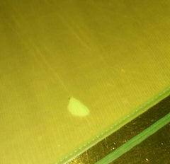
An adhesion void in an otherwise ideal
single layer print. This small defect will
be reinforced by the second layer, so a
reprint will not be necessary in this case.
First layer height:
The first layer height must be adjusted either physically or in software to give .5 to .8 of the normal layer height. Software settings should be made in the print profile to reflect this. This will allow good print leveling characteristics. Layer height and percentage should be adjusted to achieve a print line with approximately 1.25 - 1.5x nozzle diameter, with a flat profile and straight edges.
Bed flatness:
Many times, the print bed is not perfectly flat. Compensation must be made within the first layer to achieve good quality thin prints. This imposes certain constraints on the process, depending on the relative irregularity of your print bed.
Localized sieving caused by a gap
in the tape surface of the bed.
Any variation in bed height within the work footprint should not exceed .5 of your first layer height (layer height x first layer multiplier). Compensation can sometimes be made by increasing your slice layer height within the available constraints. Prints can also be constrained to a more regular area of the bed, or the bed surface can be replaced with a flatter bed.
Bed flatness problems are characterized by variations in print quality depending on its area on the bed, with some areas showing surface curling or stringing while other areas print correctly. Some minor variation may be unavoidable, and often defects will be buried under a following layer if they are not too extreme.
Surface Defects:
Surface defects include surface curling and sieving. Surface curling is characterized by a ribbon type defects along the fill print lines, resulting in a rough, higher than layer height print profile.
Surface curling indicates excessive nozzle pressure. It can be remedied by increasing the physical first layer height (adjusting the end stop), or reducing the software first layer height percentage.

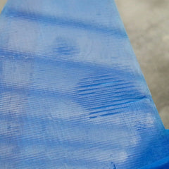
Minor curling caused by insufficient nozzle height.
In this case it was not too severe, but artifacts can
sometimes block the motion of the nozzle,
ruining the print.
Sieving is characterized by fill that is not bonded to the adjacent filaments and is sieve like and not fully contiguous. This is regularly accompanied by poor adhesion and poor structural characteristics. sieving can be remedied by decreasing the physical first layer height, or increasing the software first layer percentage.

Sieving, here caused by a low spot on the bed.
Nozzle height should be adjusted to give a
workable compromise between the high
and low areas on the print bed.
The favored mechanism for correcting first layer defects is to set the software first layer percentage to .7 of your layer height, and adjust the physical first layer height (end stops) to achieve the desired print quality. Final tuning can then be done in the software setting.
Sometimes print defect types will vary over the surface of the print. This is an usually an indication of poor bed flatness or adhesion problems.
Nozzle Pressure:
It is helpful to be aware of nozzle pressure, especially when printing membranes. High nozzle pressure causes surface curling, poor edge definition, point blobbing, corner artifacts, and stringing artifacts. Insufficient nozzle pressure results in poor adhesion, intermittent voids, and sieve like membranes.
Low nozzle pressure results from excessive physical layer height, improper filament / extruder calibration, or filament drive slippage. Sometimes low temperature can mimic low nozzle pressure by causing drive slippage.
High nozzle pressure results from insufficient physical layer height for the software settings, low temperature, poor filament / extruder calibration, or nozzle blockage.
Elasticity in the printing system, especially on bowden type (indirect) drive extruders can cause artifacting when the conditions causing the pressure buildup are temporarily relieved, such as when the head is lifted.
When printing first layers on an imperfect bed, nozzle pressure will rise as high areas are encountered, restricting flow from the nozzle. System elasticity will then cause excessive plastic to be extruded when this pressure is relieved, such as when a lower portion of the bed is encountered or the nozzle is lifted, sometimes causing gobbing or poor line definition.
In some ways this automatic flow adjustment can actually be helpful, as it creates a leveling effect, extruding less plastic on the high spots, and filling in the low ones with the surplus. The goal is to achieve the best compromise of leveling and print quality, to provide an ideal foundation for the second (and often final) layer in your membrane print.
Elasticity effects can be reduced by reducing the hot area as much as possible by cooling the extrusion barrel, using low elasticity components in your drive and extruder systems, and by careful control of filament retraction parameters.