extrusion multipliers and printing engineered structures - a technical brief October 10 2013
In FDM (fused deposition manufacturing) printers like the REPRAP and related designs, the amount of filament that the extruder deposits through the print nozzle while printing is one of the most critical factors. The calculation to arrive at the correct amount of filament to feed will be dependent upon the feedstock filament size and variability, the nozzle diameter, the extruder drive wheel tension, the extrusion temperature, and the layer height (+/- any first layer corrections).
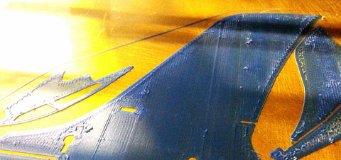
excessive material deposition caused these lumpy surfaces, most evident
where the fill ratio is 100% and there is no place for excess to go.
Sometimes, insufficient first layer height can be the actual cause
on thin structures such as this.
For aircraft and other objects where the interaction of the internal and external structure of an item works together to provide a desired function, significant deviations from optimal extrusion may cause unacceptable performance characteristics in the finished print.
Many of the aircraft designed by Handmade By Robots here at threedsy.com are engineered to flex in very specific ways in response to environmental factors such as airspeed, g-loading, gravity, and -especially in the case of the cumulus- even air currents and thermals (it is designed to resist the natural tendency to turn our of buoyant air by twisting at the wingtips).
The flying wing series develops its proper airfoil and reflex shape by a complex interaction of bending forces created when the dihedral clip, the wing hinge, the unhinged portions of the wing, and the vertical stabilizers / reflex formers interact in the assembled model.
Due to these design considerations, as well as cosmetic factors, it is highly desirable to optimize the extrusion process as much as possible so as to preserve the designed in flight characteristics, minimize weight, and to end up with an attractive, true flying model.

A small deficit of material causes the upper surface to fuse
incompletely, resulting in porosity and a lack of rigidity.
Assuming that your extruder is properly calibrated in the firmware, and the G-code generating program you use has good numbers for your filament and nozzle size, a reasonably midrange extrusion temperature, and an accurate idea of the actual first layer height, you should get reasonable extrusion quality barring problems with extruder drive function or adjustment.
For -optimal- printing, such as may be required for highly engineered pieces (such as functional items, or items designed to flex in very specific ways, such as aircraft) some fine tuning may be required. The goal is to deposit just enough material to provide solid fill of solid objects, without excess or voids of any kind. In practice, this can be very difficult, as feedstock filament size has some variability, and this variability is magnified and directly expressed in the extrusion process.
The "fudge factor" used to compensate for minor mis-calibration or filament variation is the "extrusion multiplier", a simple factor applied to the overall extrusion calculation, so that 1 equals no adjustment, .95 causes a 5% reduction in filament feed, and 1.05 provides a 5% increase in feed.
In practice, a slight deficit of material is preferable to excess, which builds up on the print and can accumulate to the extent that if can cause a print head crash, ruining the print , or in less severe cases results in a globby surface. As long as the deficit is just enough to compensate for filament variability, and the filament is also reasonably uniform, any deficit or voids in the final piece will be negligible. On the other hand, if the material deficit is excessive, flimsy prints, unclosed surfaces, poor bed adhesion, and porous structures may result.
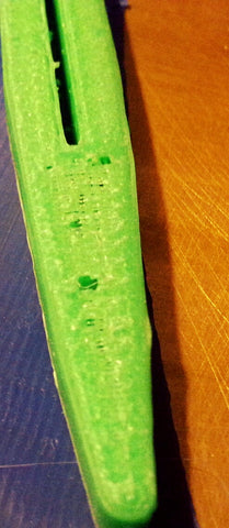
Insufficient extruded material caused these voids. In this case,
it was caused by insufficient tension on the extruder drive wheel springs.
One way to determine the proper "fudge factor" for a given combination of filament, nozzle, and extruder is to print a solid object at 100% fill. gradually increase the extrusion multiplier (by .02-.03) until the print starts to develop surplus material, which will typically be evident at the edges first as the print becomes more "messy". Then retry while reducing the multiplier by .01-.02 until the print is once again uniform. This should be close to optimal, although filament variability may cause you to back off another .01-.02 if excess material occasionally appears.
At this point you may have to readjust your first layer height multiplier to reflect the inverse of your extrusion adjustment (for example, if you -increased- extrusion by 3%, you will need to make an equivalent -reduction- at the first layer adjustment.
Having a correct extrusion calibration / multiplier will help you to make clean, high quality engineered objects that fit together and provide the performance characteristics with which they were designed.