Getting a great first layer, an important foundation for reliable 3D printing. (and super important for gliders!) September 15 2017
Getting a solid, smooth first layer is a key part of producing high quality prints. The first layer forms the critical foundation for your model, and can determine the success or failure of your print even long after the start of the printing process. Some models, such as the flying gliders here at threedsy.com, rely on a smooth first and second layer for both performance and durability.

The foundation of all 3d prints is a good first layer. First layer performance becomes even more important when printing thin structures like the wings on the high performance flying gliders available here at threedsy.com.
So, How do you print a smooth, reliable first layer? First, you will need a good printing surface that will adhere to the plastic you are printing. A PEI sheet, Build-tack, Kapton tape, glass with hairspray or glue stick, or many other solutions might work for you, depending on the machine you use and the filament that you wish to print with. My strong preference if for a PEI sheet, though adhesion with ABS is not as good as it could be.
Next, you will need to have the z-height accurately adjusted, and to be sure that your extrusion rate is accurate for your filament and extruder drive system. The exact method of adjusting the z-height zero point varies considerably from printer to printer, so I will not be addressing that directly – (you should refer to your manual for the adjustment method). Instead I will focus on tuning and testing to ensure that everything is where it needs to be.
First, warm your printer to printing temperature. Set your heated bed (if equipped) and nozzle to standard printing temperatures. You may want to retract a bit of filament to prevent oozing. Preheating is important, because the nozzle and bed can change shape slightly depending on the temperature.
Next, download this Z-Height test model. Slice it to print in the middle of the print bed with a 0.15 layer height, one lower and two upper surfaces (ideally) or two upper and two lower (0.3mm) surfaces if selecting different thicknesses for the top and bottom is not an option. Use one or two perimeters, and a 30% line infill.
After the printer is up to temperature and thermally stable (15 minutes or so) , roughly set the z-height of your printer. It may do this automatically, or you can use the manual adjustment to bring the nozzle down (bed up) to where a piece of notebook paper slides easily between the nozzle and the bed, but not completely freely...it should have a little friction.
After this initial adjustment, print the test model in the very center of the print bed. Examine the result. It should be smooth but solid. If there are spaces between the print lines on the lower (outer) step, the nozzle is too high. If there are gouges or marks / ribbons on the surface of the lower step, the nozzle is too low. Adjust your zero point as per your printer manual or build resource until the lower step is smooth and solid. When peeled up, the bottom should be smooth with barely discernible lines but no cracks or separations. If there are no lines at all on the bottom, the nozzle may be still slightly too low, or you may just be exactly on the sweet spot if the top is nice and smooth.
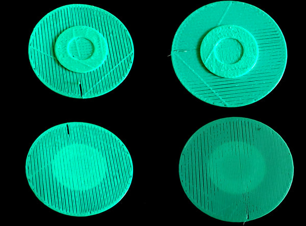
Above, typical results when the nozzle is too far from the print bed. Notice the un-fused lines, sieve like appearance, and the way that the print improves on the upper layers, indicating the problem as a first layer issue. The lines are from oozing during travel, as these pieces were printed without retraction to better illustrate the differences.

Here you can see, typical results when the nozzle is too close to the print bed. Notice the low areas where the nozzle was sealed by the print bed, and the ribbon like artifacts that squeezed out beside the head during printing. Once again, the print improves on the upper layers indicating the problem as a first layer issue.
Once the bottom step (first layer) is solid, without ribbons, gaps, or gouges, turn your attention to the upper layers.
With a good first layer but sieving at the upper layers as shown on the left in the following photo, your filament is either smaller than your settings, slipping in the extruder drive, your E-steps are too low, or your Z-axis steps are too high. Conversely, If the first layer looks good but upper layers show ribbons or gouging, your filament is probably larger than the setting, the E-steps are too high, or the Z-steps are too low. If your filament diameter is correct, your Z axis moves the distance it is commanded, and your extruder drive is feeding correctly, try adjusting the extrusion multiplier “fudge factor” setting.
Most of the time incorrect filament size is the cause. Measuring your filament diameter and giving the slicer correct information is critical to getting good results.

Shown above is an example on the left of underextrusion, and on the right of overextrusion. Note how in both cases the first layer is reasonably well adjusted, but the upper layers degrade in quality. In a properly calibrated printer, these problems are usually a result of variations variations in filament size, or sometimes in the case of underextrusion (left) due to extruder drive slippage.

Shown here is a reasonably good test example. Note the slight overextrusion near the ends of the print lines. Depending on your printer and software, these may be a normal result of minor imperfections in the acceleration algorithm or due to bonding overlap between the edge and the fill of the layer.
Once you can get a reasonably good first layer in the center of your print bed, the next step is to adjust your bed to be perpendicular to the z-axis (usually called bed “leveling”). This should enable you to get a good first layer on the entire print bed. Most heated beds bulge up a little in the center due to temperature distribution variations, so precise control of this will likely require software compensation for bed irregularities. Thankfully, this feature is built into most modern firmware...if your printer doesn't have it, look into any firmware updates that could provide this important capability.


